

In the field of mechanical manufacturing, the dimensional accuracy of parts directly determines the quality and performance of the products. The go/no-go gauge (also known as the limiting gauge), this seemingly simple tool, is precisely the standard used in industrial production to ensure the qualification of part dimensions. When conducting "straight thread processing" of reinforcing bars in the engineering industry, the go/no-go gauge is also frequently used to inspect the quality. So, what are the go/no-go gauge and how is it used?

General Overview of Gauge Rods and Stop Rods
The gauge block and the stop gauge are two common types of limit gauges used in mechanical manufacturing and inspection, falling under the category of precision measuring tools. They are designed based on the Taylor principle and are used to quickly test whether the dimensions of the workpiece are within the specified tolerance range without the need to read specific values.
The go gauge is a measuring tool used to check the minimum dimensional size of a workpiece (that is, the minimum size of a hole or the maximum size of an axis). If the go gauge can pass through or fit into the workpiece smoothly, it indicates that the workpiece size has at least met the minimum dimensional size requirement.
A stop gauge (No-Go Gauge) is a measuring tool used to check the maximum dimensional size of a workpiece (either the maximum size of a hole or the minimum size of an axis). A qualified workpiece should be able to prevent the stop gauge from passing through or entering. If the stop gauge can pass through, it indicates that the workpiece size has exceeded the maximum allowable value.
The working principles of the gauge block and the stop gauge
The design of the gauge block and the stop gauge is based on the principle of judging by the limit dimensions:
The gauge should be designed as a full-form gauge, meaning that its measuring surface should have the same complete shape as the measured element (such as cylindrical or rectangular), and its length should be equal to the mating length, which is used to control the actual size of the workpiece.
The gauge should be designed as a two-point gauge to control the actual size of the workpiece. For hole gauges, they are usually flat; for shaft gauges, they are usually in the form of chuck gauges.
This design ensures that the gauge ring can comprehensively test the overall errors of the workpiece (such as shape errors and dimensional errors), while the stop rule focuses on testing the local actual dimensions.
Types of gauge blocks and stop blocks
1.Screw Plug Gauge
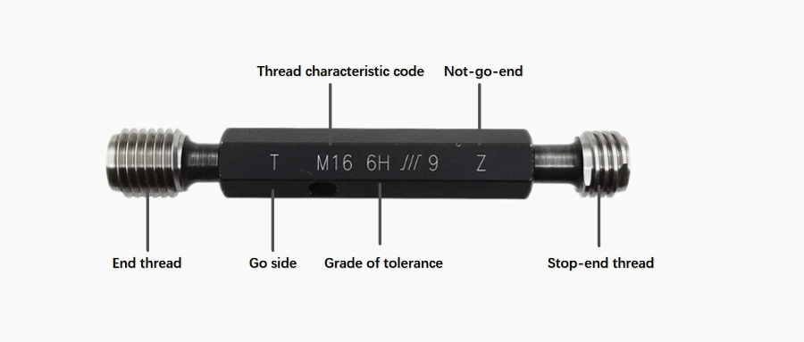
General rule: The go-end of the plug gauge simulates the insertion process of the mating part;
Gauge: For the stop end of the plug gauge, only the local part of the hole size exceeding the standard needs to be inspected.
2.thread ring gauge
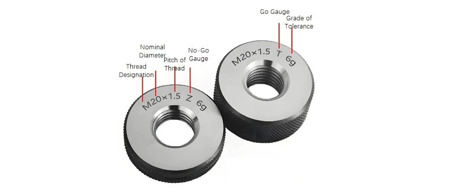
General rule: Must completely cover the shaft;
Gauge: Only checks whether the shaft diameter is too small.
The usage methods of the gauge block and the stop gauge
Operation steps (taking the detection hole as an example)
1. Using the gauge:
Insert the tapered end of the plug gauge vertically into the hole. Use only the self-weight or a slight pressure (do not forcefully strike). If the tapered end can pass through the entire length of the hole naturally, then the hole diameter is not less than the lower limit;
2. Using gauge blocks:
Insert the stop end of the plug gauge into the hole. If the gauge block cannot extend more than 1-2mm beyond the hole (the specific standard depends on industry regulations), then the hole diameter does not exceed the upper limit.
Example:
A hole with an aperture marked as "Φ10H7" (tolerance range: Φ10.000 - 10.015mm):
The diameter of the gauge block is designed to be 10.000mm (minimum aperture), if the gauge block can be inserted into the hole, it indicates that the hole is not smaller than the lower limit;
the diameter of the stop gauge is designed to be 10.015mm (maximum aperture), if the stop gauge cannot be inserted, it indicates that the hole is not exceeding the upper limit.
The gauge and the plug are complementary tools in traditional manufacturing processes. The gauge helps determine the basic framework and proportions of the design, while the plug ensures the standardization and stability of the detailed dimensions. Correct and standardized use of the gauge and the plug is one of the key methods to ensure the interchangeability and assembly quality of mechanical parts.

Let's Make Something Extraordinary Together
At Dahong Precision, we are more than just a CNC machining supplier, we are your partner in precision manufacturing. Whether you need simple parts or highly complex parts, our 3, 4 and 5 axis CNC machining services deliver the quality and reliability you deserve. Contact us today to discuss your project and find out how we can help you achieve your goals.


