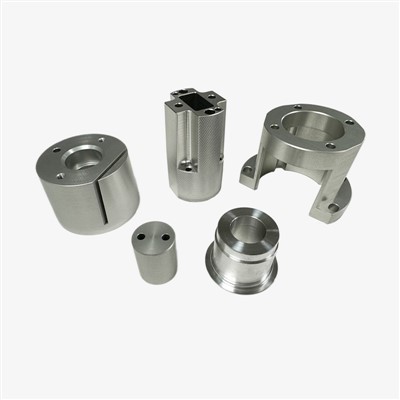
Precision ground die components are interchangeable working elements engineered for progressive stamping dies, plastic injection molds, and high-load industrial fixtures. They locate, guide, and shape material under intense cyclic mechanical stress.
Applications include processing high-strength steel sheets, non-ferrous metals, and engineered polymers across blanking, piercing, bending, and injection molding operations.
Production relies on multi-axis CNC grinding (surface, cylindrical, and profile), high-precision wire EDM, and controlled vacuum heat treatment. Dimensional accuracy reaches within +/-0.001 mm, securing absolute tool interchangeability and minimizing assembly downtime during maintenance.
Technical Specifications
|
Parameter |
Specification Range |
|
Material |
SKD11, D2, ASP23, CPM 10V, Tungsten Carbide (YG6/YG8), 1.2379, 1.2343 |
|
Size Range |
Diameter: Diameter 1 mm - 200 mm; Length: Up to 500 mm (Custom sizes per customer drawing) |
|
Tolerance |
+/-0.001 mm to +/-0.005 mm |
|
Linear Accuracy |
Straightness and flatness within 0.002 mm / 100 mm |
|
Surface Roughness |
Ra 0.05 um - 0.4 um |
|
Processing Range |
Turning, CNC Milling, Jig Grinding, Wire EDM, Sinker EDM, Surface Grinding |
|
Equipment & Process |
Studer Cylindrical Grinders, Mitsui Surface Grinders, Charmilles Wire EDM, Vacuum Hardening Furnaces |
Key Features
Dimensional Accuracy: Ground to tight tolerances down to +/-0.001 mm, eliminating secondary hand-fitting during die stack assembly.
Repeatability: Strict geometric control ensures uniform interchangeability across multi-cavity dies and high-volume production runs.
Complex Geometry: Multi-axis CNC grinding and micro-EDM accommodate intricate profiles, stepped diameters, and blind keyways.
Small Batch Production: Flexible setup handles low-volume custom replacements and urgent prototype tooling without extra tooling surcharges.
Surface Quality: Mirror-polished or specialized low-friction finishes (Ra <= 0.1 um) reduce galling and extend working lifecycles.
Tight Tolerances: Controlled thermal stabilization and deep cryogenic treatment eliminate residual material stress, preventing distortion during operation.
Applications
Automotive: Progressive stamping dies for structural chassis parts, seat mechanisms, and electrical connector terminals.
Medical: Multi-cavity injection molds for surgical instrument housings and high-purity polymer components.
Aerospace: Precision trimming dies and holding fixtures for high-temperature alloy sheet metal components.
Automation: High-wear guide pins, bushings, and locating pins for high-speed automated assembly lines.
Electronics: Miniature connector dies and lead-frame stamping tools requiring sub-micron positioning.
Industrial Equipment: Heavy-duty punching and shearing tools for industrial hardware manufacturing.
Materials & Surface Finishes
Material Options
Tool Steels: SKD11, D2, O1, A2
Powder Metallurgy (PM) Steels: ASP23, ASP30, CPM 10V (high wear and impact resistance)
Tungsten Carbide: Cobalt-bonded carbides for extreme abrasive resistance
Engineering Alloys: Stainless steels (440C, 1.4112) for corrosive working environments
Surface Finishes & Treatments
Vacuum Heat Treatment: Controlled hardening yielding consistent ranges from HRC 58 to HRC 64 with optimized core toughness.
Cryogenic Treatment: Deep cryogenic processing at -196 deg C to transform retained austenite and stabilize dimensional structure.
PVD Coatings: TiN, TiCN, AlTiN, and DLC (Diamond-Like Carbon) applied to lower the friction coefficient and enhance wear resistance.
Customization & OEM
Drawing / CAD Files: Accept formats including STEP, IGES, DXF, DWG, and PDF. Full engineering DFM review provided prior to manufacturing.
Custom Dimensions: Manufactured precisely to customer blueprints, including non-standard diameters, custom shank lengths, and specialized relief cuts.
Tolerance Requirements: Execution of specialized fit classes (e.g., g6, h6, JS7) and custom tolerance zones per assembly specifications.
Material Selection: Engineering consultation available to match material grades to specific workpiece hardness and press speeds.
Prototype & Mass Production: Scalable workflow accommodates single-piece urgent replacements to production batches exceeding 10,000 units.
Quality Control
CMM Inspection: Hexagon Coordinate Measuring Machines verify 3D complex geometries and spatial positional tolerances.
Dimensional Inspection: Micrometers, air gauges, and optical comparators verify diameters, lengths, and concentricity within micron limits.
Surface Roughness Testing: Mitutoyo profilometers measure Ra and Rz parameters to verify finish consistency across batches.
Material Inspection: Spectrometer material verification and Rockwell/Leeb hardness testing ensure uniform core and surface hardness.
Final Inspection: 100% dimensional check on critical interface surfaces prior to anti-corrosion packaging. Inspection report supplied with each shipment.
Packaging & Delivery
Protective Packaging: Individual VCI (Volatile Corrosion Inhibitor) anti-rust paper wrapping, vacuum-sealed plastic bags, and dense foam-lined slots.
Batch Identification: Laser-etched part numbers, material grades, and heat lot numbers on each component for complete traceability.
Export Packaging: Sturdy double-walled corrugated cartons with custom wooden crating for heavy shipments.
Lead Time:
Standard custom components: 7 - 12 business days.
Complex geometries / Powder metallurgy materials: 15 - 20 business days.
Expedited prototyping service available upon request.
FAQ
Request a Quote
To receive a formal quotation within 24 hours, submit the following technical details:
- Part Drawing / 3D CAD File (PDF, STEP, or IGES format with explicit tolerances)
- Material Grade (e.g., SKD11, ASP23, Carbide)
- Quantity Required (Prototype vs. Batch Production)
- Tolerance Requirements & Surface Finish Specifications
- Target Delivery Timeline
[Upload Drawing & Request Quote] (Direct Engineering Review)
Hot Tags: precision ground die components, China precision ground die components manufacturers, suppliers, factory