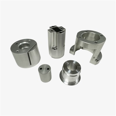
Swiss CNC turned shafts are high-precision cylindrical components manufactured through sliding-headstock machining, designed for applications with strict geometric tolerances and high length-to-diameter ratios. This process integrates simultaneous turning and live tooling to produce multi-step diameters, cross-holes, flats, and threads in a single setup, eliminating repositioning errors and ensuring strict coaxiality for critical OEM assemblies.
Technical Specifications
|
Parameter |
Specification Range |
|
Material |
Stainless Steel (303, 304, 316, 17-4PH), Carbon/Alloy Steel (12L14, 4140, 8620), Brass, Aluminum (6061, 7075), Titanium |
|
Size / Diameter |
Diameter 1 mm - 32 mm (up to Diameter 38 mm with guide-bushingless setup) |
|
Length Capacity |
Up to 300 mm |
|
Dimensional Tolerance |
Down to +/-0.005 mm (or tighter per engineering requirements) |
|
Geometric Accuracy |
Cylindricity and Runout within 0.005 mm |
|
Surface Roughness |
Up to Ra 0.4 micrometer (as-machined) |
|
Processing Range |
Turning, axial/radial drilling, milling, thread whirling, knurling, slotting |
|
Equipment / Process |
Multi-axis Swiss CNC Lathes (Tsugami / Star / Citizen) with sub-spindles and live tooling |
Key Features
Tight Tolerances: Maintains dimensional control down to +/-0.005 mm across multi-diameter steps, supporting precision bearing fits and mating assemblies.
Exceptional Repeatability: Sliding headstock design supports slender parts close to the tool guide bushing, minimizing deflection and vibration during long production runs.
Complex Geometry Integration: Combines turning, off-center milling, cross-drilling, and threading in a single clamping operation to eliminate cumulative positioning errors.
High Aspect Ratio Production: Efficiently machines parts with high length-to-diameter ratios without structural distortion or chatter marks.
Controlled Surface Quality: Delivers consistent as-machined finishes down to Ra 0.4 micrometer, reducing or eliminating secondary finishing operations.
Optimized Small & Medium Batches: Setups configured for efficient transition between prototype validation and volume production runs.
Applications
Automotive: Fuel injection components, sensor pins, actuator shafts, and small transmission valve spools.
Medical: Surgical instrument shafts, bone screw blanks, dental drill components, and diagnostic equipment spindles.
Aerospace: Actuator pins, micro-valve components, instrument drive shafts, and fastener hardware.
Automation: Linear guide shafts, stepper motor shafts, encoder axles, and robotic joint pins.
Electronics: Micro-connectors, housing standoffs, coaxial pins, and switch actuators.
Industrial Equipment: Pump shafts, valve stems, precision gear shafts, and fastening spindles.
Materials & Surface Finishes
Material Options
Stainless Steel: 303, 304, 316/316L, 17-4PH, 420
Carbon & Alloy Steel: 12L14, 1045, 4140, 8620, 52100
Aluminum: 6061-T6, 7075-T6, 2024
Brass & Copper: C36000 (Free-cutting brass), C11000 Copper
Engineering Plastics: POM (Delrin), PEEK, PTFE, Nylon
Surface Finish Options
- Passivation (ASTM A967 / QQ-P-35 for stainless steel)
- Electroless Nickel Plating
- Anodizing (Type II and Type III Hardcoat for aluminum)
- Zinc Plating (Clear, Yellow, or Black trivalent chromate)
- Black Oxide / Thermal Blackening
- Micro-blasting / Glass bead blasting for deburring and matte finish
Customization & OEM
Production is executed strictly to customer specifications based on provided print documentation.
Drawing / CAD Files: Accepts STEP, IGES, Parasolid, DXF, and 2D PDF engineering drawings. GD&T callouts are programmed directly into CAM software.
Custom Dimensions: Diameter, length, step transitions, and profile features built precisely to print specifications.
Tolerance Requirements: Custom fits, tight concentricity, and specific geometric dimensioning and tolerancing (GD&T) adhered to per print.
Material Selection: Certified raw materials sourced from traceable mills with full Material Test Reports (MTRs) provided upon request.
Prototype & Mass Production: Flexible scheduling supporting low-volume prototyping (10 to 50 pieces) through to high-volume production runs (10,000+ pieces).
Quality Control
CMM Inspection: 3D coordinate measuring machine verifies complex spatial dimensions and geometric tolerances.
Dimensional Inspection: Optical comparators, micrometer sets, plug gauges, and air gauges used for in-process and final verification.
Surface Roughness Testing: Contact profilometers measure Ra values against engineering thresholds.
Material Inspection: Incoming raw material verified via spectrometer material analysis and mill test report cross-referencing.
Final Inspection: 100% attribute inspection or AQL sampling plans executed per customer quality agreement prior to shipment.
Packaging & Delivery
Protective Packaging: Individual slot packaging, VCI (Volatile Corrosion Inhibitor) anti-rust paper, or vacuum-sealed blister packs to prevent transit damage or oxidation.
Batch Identification: Clear barcode labeling on every package indicating part number, revision, batch number, and quantity.
Export Packaging: Sturdy double-walled corrugated cartons palletized and strapped for international air or ocean freight.
Lead Time: Prototypes delivered in 7 to 12 business days; production runs scheduled per release schedules (typically 3 to 5 weeks).
FAQ
Request a Quote
To receive a detailed quotation within 24 hours, submit the following technical data to our engineering team:
Part Drawing: 2D PDF containing critical dimensions, tolerances, and thread specifications.
3D CAD File: STEP or IGES format for accurate feature analysis and programming.
Material Specification: Exact alloy designation (e.g., Stainless Steel 303, 4140 Steel).
Order Quantity: Annual volume and projected batch sizes.
Quality Requirements: Specific inspection reports or surface finish treatments required.
Hot Tags: swiss cnc turned shafts, China swiss cnc turned shafts manufacturers, suppliers, factory